CPS Question and answers
| Que.No | Question/Problem | marks | Link |
|---|---|---|---|
| Q 2 a ) |
Question:
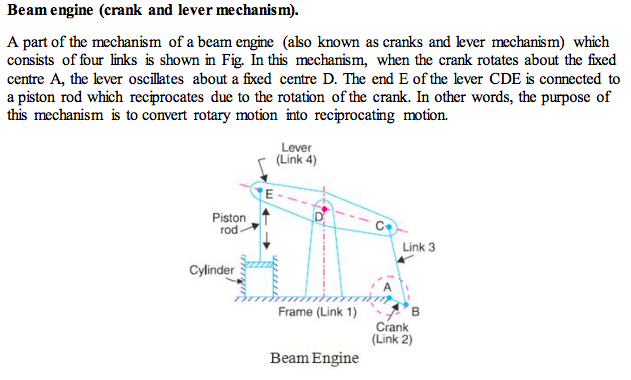
Draw a neat sketch and explain working of beam engine. Answer:
 |
4 |
view |
| Q 2 c ) |
Question:
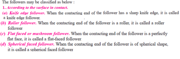
Draw and explain in short, types of followers used in cam and follower. Answer:
|
4 |
view |
| Q 2 d ) |
Question:
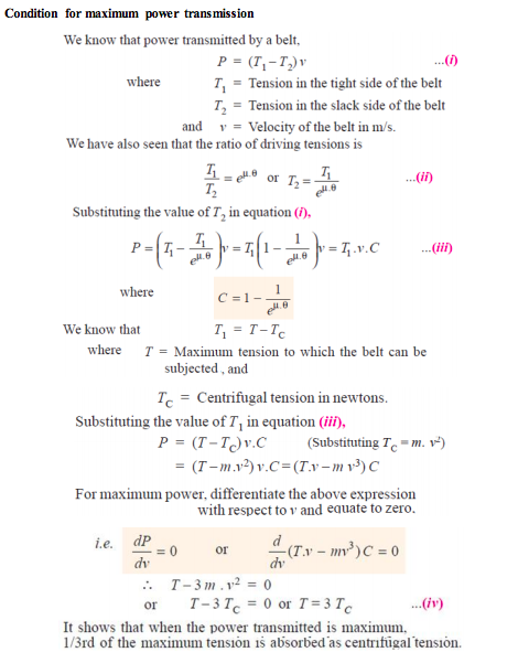
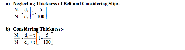
Explain condition for maximum power transmission. Answer:
 |
4 |
view |
| Q 2 e ) |
Question:
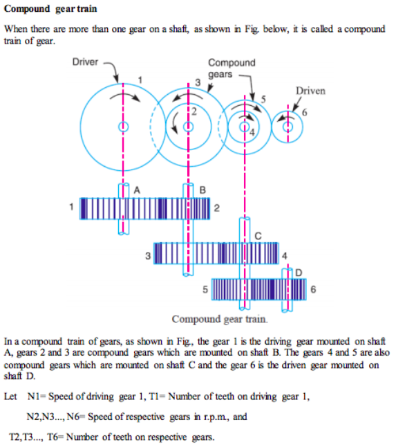
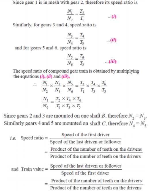
Explain the compound gear train with neat sketch and write down the velocity ratio’s equation. Answer:
  |
4 |
view |
| Q 3 a ) |
Question:
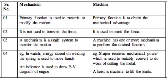
Differentiate between mechanism and machine. Answer:
 |
4 |
view |
| Q 3 b ) |
Question:
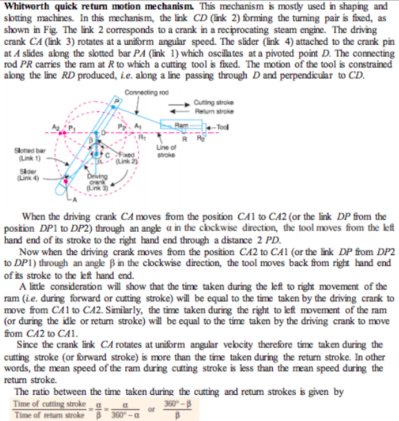
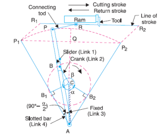
Explain the working of Whitworth quick return mechanism. Answer:
 |
4 |
view |
| Q 3 e ) |
Question:
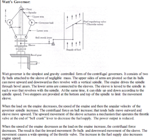
Explain the working of Watt governor with neat diagram. Answer:
 |
4 |
view |
| Q 3 f ) |
Question:
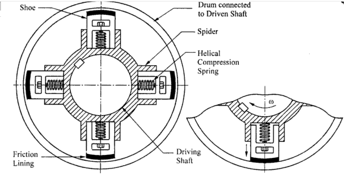
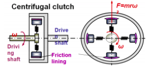
Explain the working of centrifugal clutch with neat sketch. Answer:
|
4 |
view |
| Q 4 a ) |
Question:
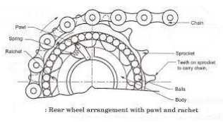
Explain the working of freewheel mechanism of bicycle with sketch. Answer:
|
4 |
view |
| Q 4 c ) |
Question:
What are the advantages of ‘V’ belt drive over flat belt drive ? Answer:
|
4 |
view |
| Q 4 d ) |
Question:
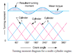
Explain the working of flywheel with the help of turning moment diagram. Answer:
|
4 |
view |
| Q 4 e ) |
Question:
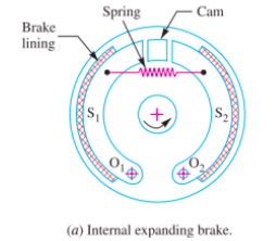
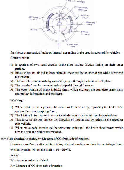
Explain the working of internal expanding brake with neat sketch. Answer:
|
4 |
view |
| Q 6 a ) |
Question:
Draw a neat sketch of Oldham’s coupling and explain the working of it. Answer:
 |
4 |
view |
| Q 6 b ) |
Question:
Define following terms : Fluctuation of energy, co-efficient of fluctuation of energy, co-efficient of fluctuation speed, maximum fluctuation of energy. Answer:
|
4 |
view |
| Q 6 c ) |
Question:
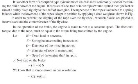
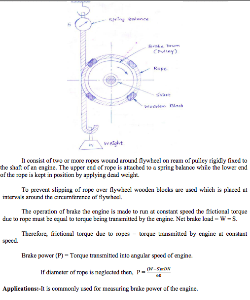
Explain the working of rope brake dynamometer with neat sketch Answer:
  |
4 |
view |
| Q 6 d ) |
Question:
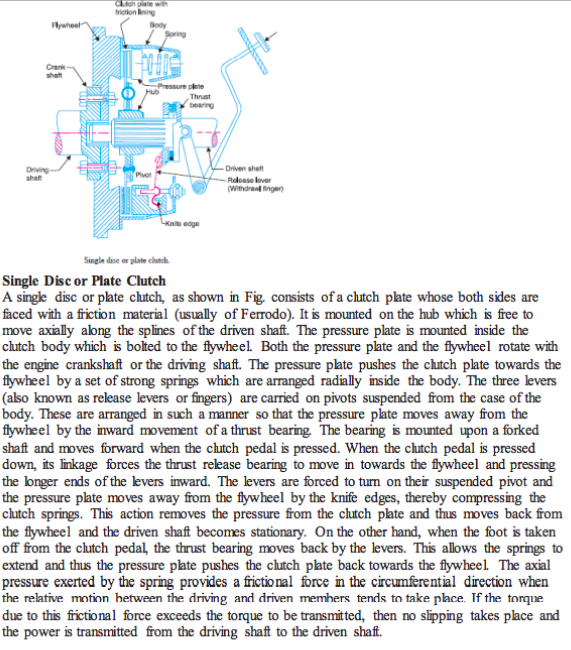
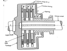
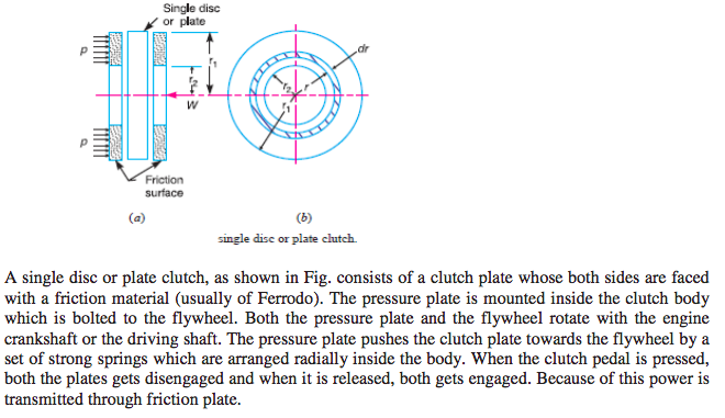
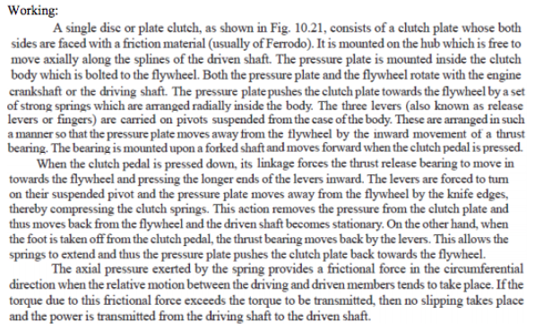
Explain the working of single plate clutch with neat diagram. Answer:
 |
4 |
view |
| Q 6 e ) |
Question:
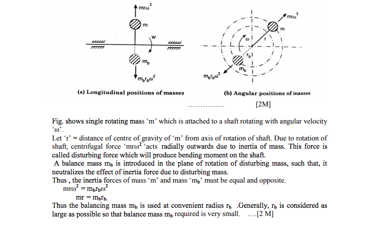
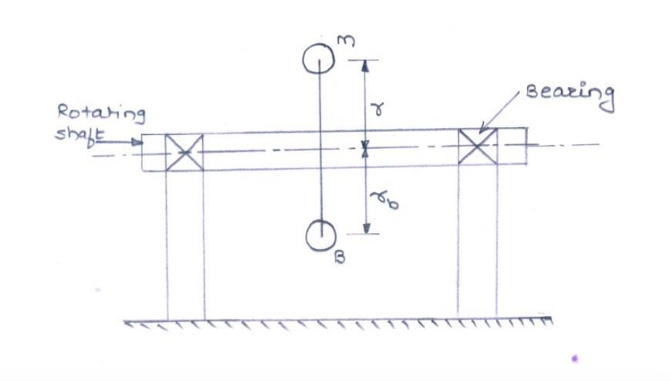
State reasons for balancing of rotating elements of machine. Explain balancing concept. Answer:
|
4 |
view |
| Que.No | Question/Problem | marks | Link |
|---|---|---|---|
| Q 1 b ) |
Question:
State any four types of friction clutch, along with its application each. Answer:
|
4 |
view |
| Q 1b)(a) |
Question:
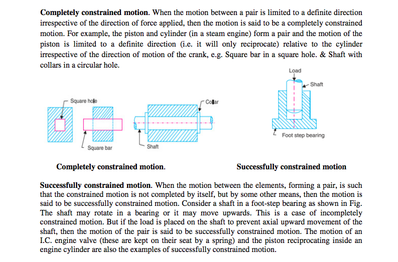
Define completely constrained motion and successfully constrained motion with neat sketch. State one example of each. Answer:
|
4 |
view |
| Q 1b)(b) |
Question:
State function of clutch. Explain working principle of clutch. Answer:
|
4 |
view |
| Q 2 a ) |
Question:
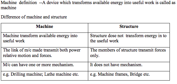
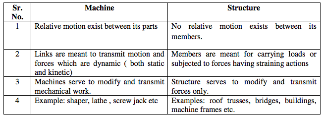
What is a machine ? Differentiate between a machine and a structure. Answer:
Machine Structure All parts / links have relative motion No relative motion between the links It transforms the available energy into some useful work No energy transformations The kinematic link of a machine may transmit both power and motion The member of the structure transmit forces only Examples: I.C. Engine, Machine tools, steam engine, type writer, etc. Example: Truss of roof, frame of machine, truss of bridge Studied under 'Dynamics' Studied under 'Statics' |
4 |
view |
| Q 2 a ) |
Question:
Differentiate between machine and structure. Answer:
Machine Structure All parts / links have relative motion No relative motion between the links It transforms the available energy into some useful work No energy transformations The kinematic link of a machine may transmit both power and The member of the structure transmit forces only |
4 |
view |
| Q 2 b ) |
Question:
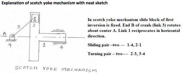
Describe with neat sketch the working of scotch yoke mechanism. Answer:
|
4 |
view |
| Q 2 b ) |
Question:
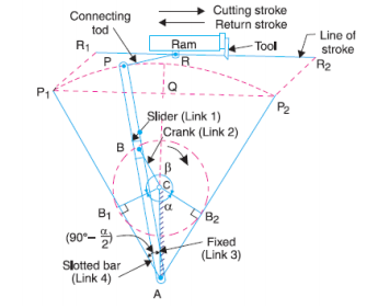
Explain with the neat sketch working of crank and slotted lever quick return mechanism. Answer:
|
4 |
view |
| Q 2 c ) |
Question:
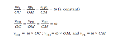
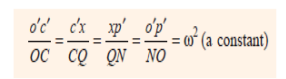
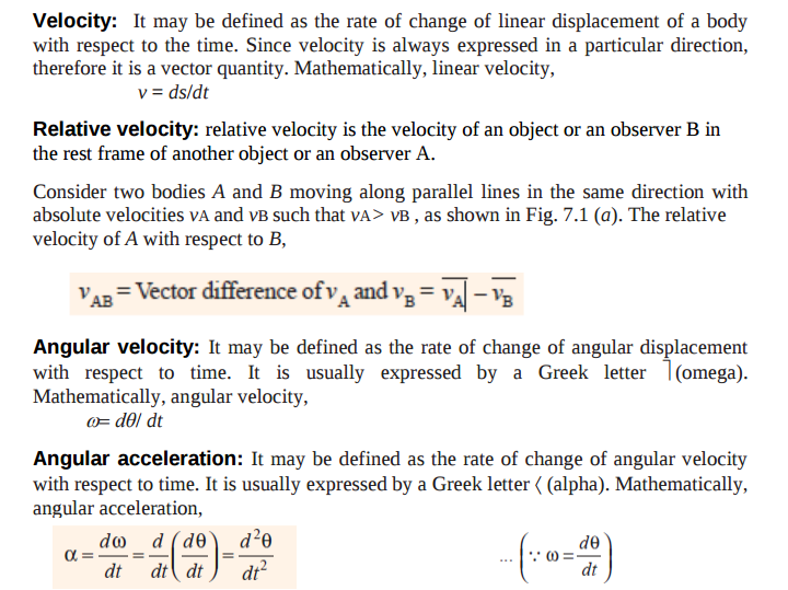
Explain the inter-relation between linear and angular velocity, linear and angular acceleration with suitable example. Answer:
  |
4 |
view |
| Q 2 c ) |
Question:
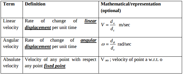
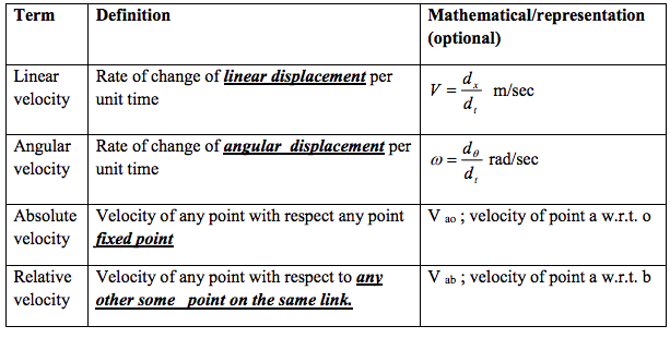
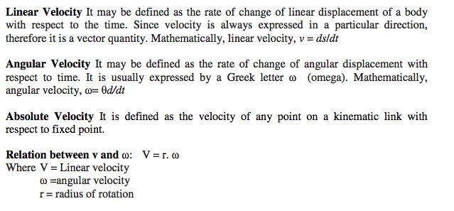
Define linear velocity, angular velocity, absolute velocity and state the relation between linear velocity and angular velocity Answer:
 |
4 |
view |
| Q 2 d ) |
Question:
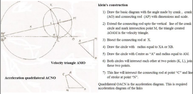
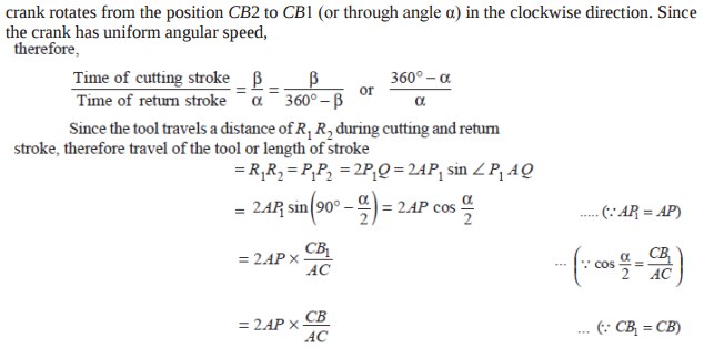
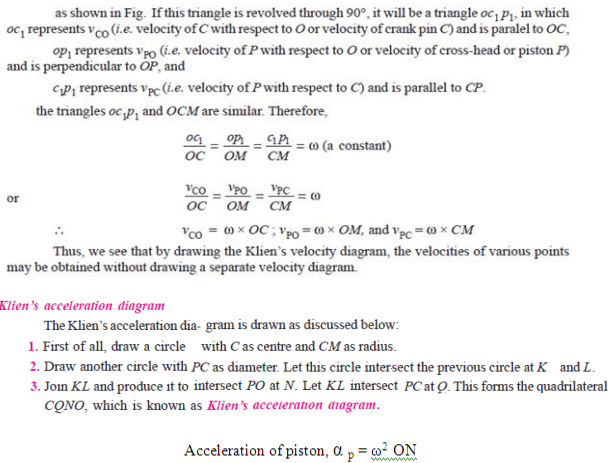
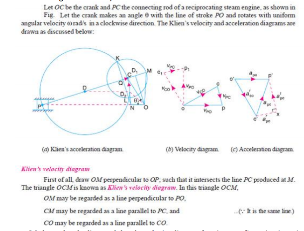
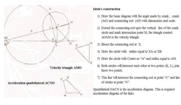
Explain the Klein’s construction to determine velocity and acceleration of a link in an I.C. engine mechanism. Answer:
|
4 |
view |
| Q 2 d ) |
Question:
Explain the Klein’s construction to determine velocity and acceleration of single slider crank mechanism Answer:
 |
4 |
view |
| Q 2 e ) |
Question:
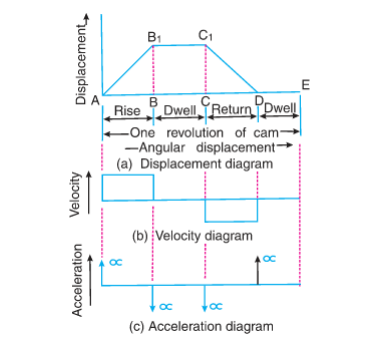
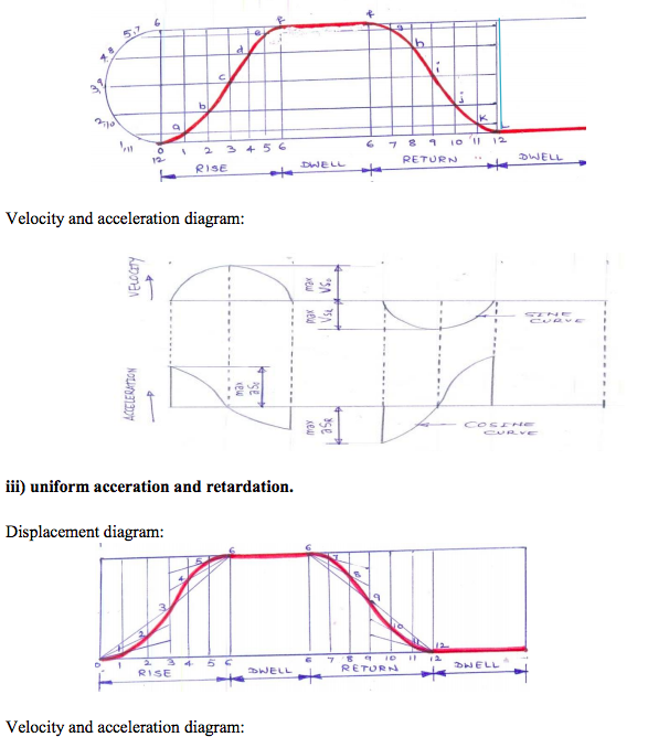
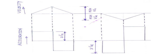
Draw the labelled displacement, velocity and acceleration diagrams for a follower when it moves with simple harmonic motion. Answer:
|
4 |
view |
| Q 2 e ) |
Question:
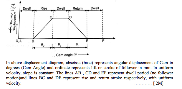
Draw the labelled displacement, velocity and acceleration diagrams for a follower when it moves with uniform velocity. Answer:
 |
4 |
view |
| Q 2 f ) |
Question:
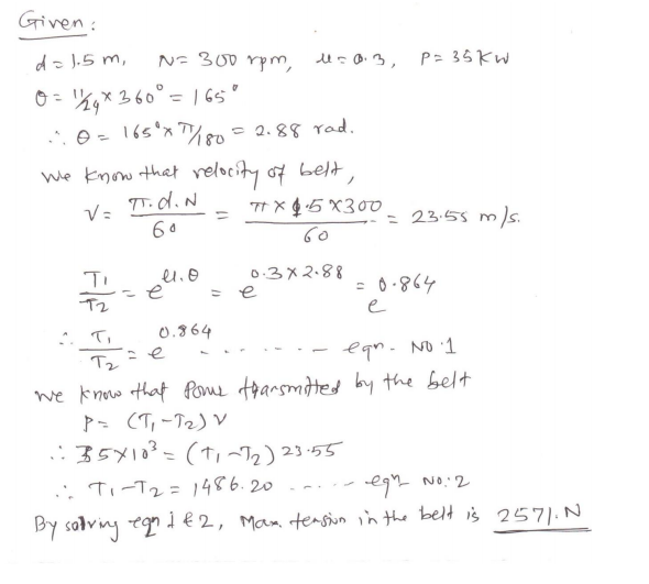
A flat belt drive is required to transmit 35 kW from a pulley of 1.5 m effective diameter running at speed of 300 rpm. The angle of contact is spread over 11/24 of the circumference co-efficient of friction for the surface is 0.3. Determine the maximum tension in the belt. Answer:
 |
4 |
view |
| Q 2 f ) |
Question:
A pulley rotating at 50 m/s transmits 40 kW. The safe pull in belt is 400 N/cm width of belt. The angle of lap is 170º. If coefficient of friction is 0.24, find required width of belt. Answer:
|
4 |
view |
| Q 3 a ) |
Question:
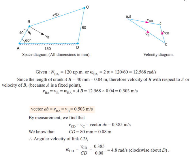
In a four bar chain ABCD, AD is fixed and is 150 mm long. The crank AB is 40 mm long and rotates at 120 r.p.m. clockwise, while the link CD = 80 mm oscillates about D. BC and AB are of equal length. Find the angular velocity of link CD when angle BAD = 60. Answer:
 |
4 |
view |
| Q 3 b ) |
Question:
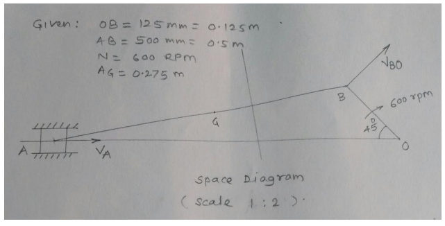
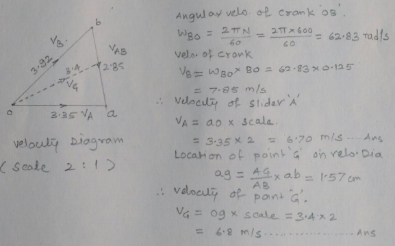
In a slider crank mechanism, the length of crank OB and connecting rod AB are 125 mm and 500 mm respectively. The centre of gravity G of the connecting rod is 275 mm from the slider. The crank speed is 600 rpm clockwise. When the crank has turned 45 from the inner dead centre position, determine : (i) Velocity of slider ‘A’, (ii) Velocity of the point ‘G’ graphically. Answer:
  |
4 |
view |
| Q 3 c ) |
Question:
Explain slip and creep phenomenon in belts. Answer:
|
4 |
view |
| Q 3 d ) |
Question:
Draw the neat sketch of diaphragm clutch and explain its working. Answer:
|
4 |
view |
| Q 3 e ) |
Question:
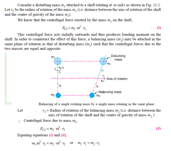
Write the procedure for balancing of a single rotating mass by single masses rotating in the same plane. Answer:
|
4 |
view |
| Q 3 f ) |
Question:
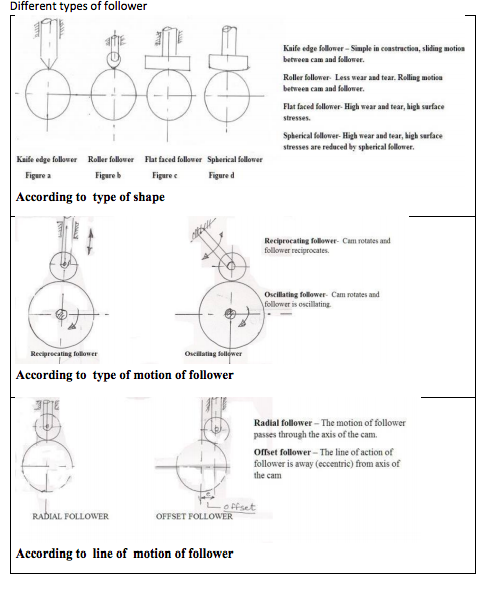
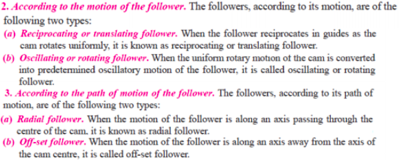
Give detailed classification of followers. Answer:
|
4 |
view |
| Q 4 a ) |
Question:
State advantages and disadvantages of chain drive over belt drive Answer:
|
4 |
view |
| Q 4 b ) |
Question:
Justify that slider crank mechanism is a modification of the basic four bar mechanism with neat sketch. Answer:
|
4 |
view |
| Q 4 c ) |
Question:
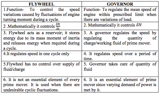
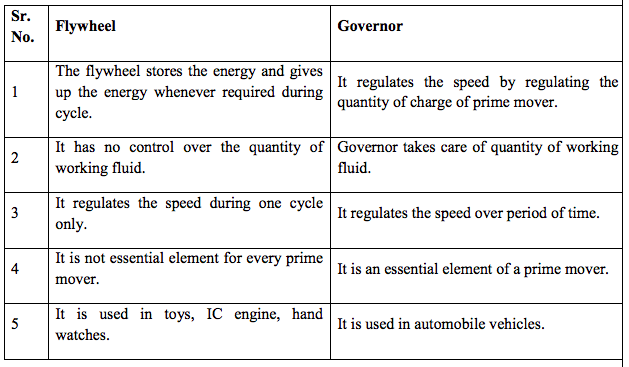
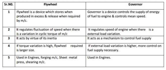
Compare flywheel and governor. Answer:
|
4 |
view |
| Q 4 d ) |
Question:
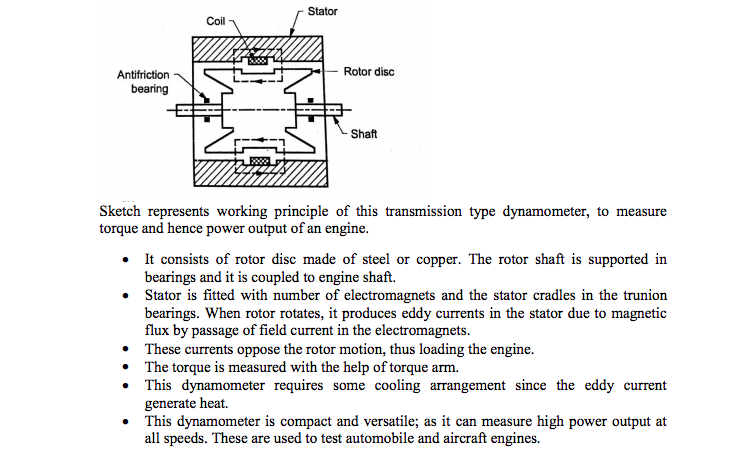
Explain with neat sketch construction and working of eddy current dynamometer. Answer:
|
4 |
view |
| Q 4 e ) |
Question:
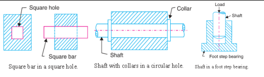
A flat foot step bearing 225 mm in diameter supports a load of 7500 N. If the co-efficient of friction is 0.09 and the shaft rotates at 600 rpm, calculate the power lost in friction. Answer:
|
4 |
view |
| Q 4 f ) |
Question:
Four masses attached to a shaft and their respective radii of rotation are given as : Answer:
|
4 |
view |
| Que.No | Question/Problem | marks | Link |
|---|---|---|---|
| Q a)(ii) |
Question:
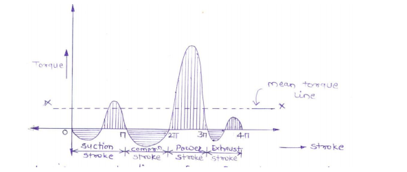
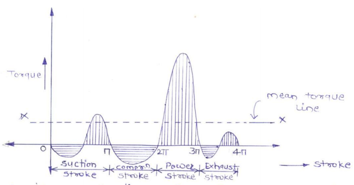
Explain single cylinder 4-stroke I.C. engine using turning moment diagram. Answer:
|
4 |
view |
| Q 1b)(i) |
Question:
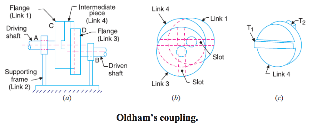
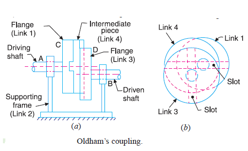
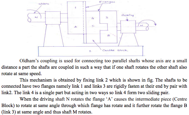
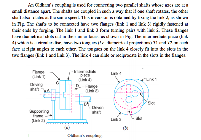
State inversions of double slider crank chain. Explain Oldham's coupling with neat sketch Answer:
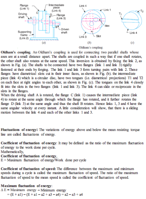
i.Scotch Yoke mechanism. ii.Oldham’s coupling. iii. Elliptical trammel. An Oldham’s coupling is used for connecting two parallel shafts whose axes are at a small distance apart. The shafts are coupled in such a way that if one shaft rotates, the other shaft also rotates at the same speed. This inversion is obtained by fixing the link 2, as shown in Fig. The shafts to be connected have two flanges (link 1 and link 3) rigidly fastened at their ends by forging. The link 1 and link 3 form turning pairs with link 2. These flanges have diametrical slots cut in their inner faces, as shown in Fig. The intermediate piece (link 4) which is a circular disc, have two tongues (i.e. diametrical projections) T1 and T2 on each face at right angles to each other. The tongues on the link 4 closely fit into the slots in the two flanges (link 1 and link 3). The link 4 can slide or reciprocate in the slots in the flanges. (link 4) to rotate at the same angle through\ which the flange has rotated, and it further rotates the flange D (link 3) at the same angle and thus the shaft B rotates. Hence links 1, 3 and 4 have the same angular velocity at every instant. A little consideration will show that there is a sliding motion between the link 4 and each of the other links 1 and 3. |
4 |
view |
| Q 1b)(ii) |
Question:
Explain: (i) Uniform pressure theory. (ii) Uniform wear theory in clutches and bearing. Answer:
When the mating component in clutch, bearing are new, then the contact between surfaces may be good over the whole surface. It means that the pressure over the rubbing surfaces is uniform distributed. This condition is not valid for old clutches, bearings because mating surfaces may have uneven friction. The condition assumes that intensity of pressure is same. P = W/A =Constant; where, W= load, A= area (ii) Uniform wear theory in clutches and bearings: parts of the rubbing surfaces will not move with the same velocity. The velocity of rubbing surface increases with the distance from the axis of the rotating element. It means that wear may be different at different radii and rate of wear depends upon the intensity of pressure (P) and the velocity of rubbing surfaces (V). It is assumed that the rate of wear is proportional to the product of intensity of pressure and velocity of rubbing surfaces. This condition assumes that rate of wear is uniform; P*r = Constant; where, P = intensity of pressure, r = radius of rotation. |
4 |
view |
| Q 1b)(iii) |
Question:
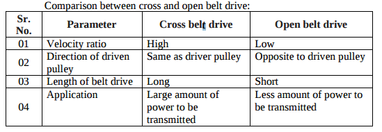
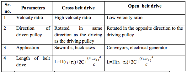
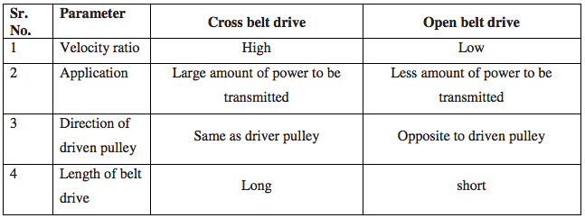
Compare cross belt drive and open belt drive on the basis of: (i) Velocity ratio. (ii) Direction of driven pulley. (iii) Length of belt drives (iv) Application. Answer:
 |
4 |
view |
| Q 2 a ) |
Question:
Draw a labeled sketch of quick return mechanism of shaper and explain its working? Answer:
|
4 |
view |
| Q 2 b ) |
Question:
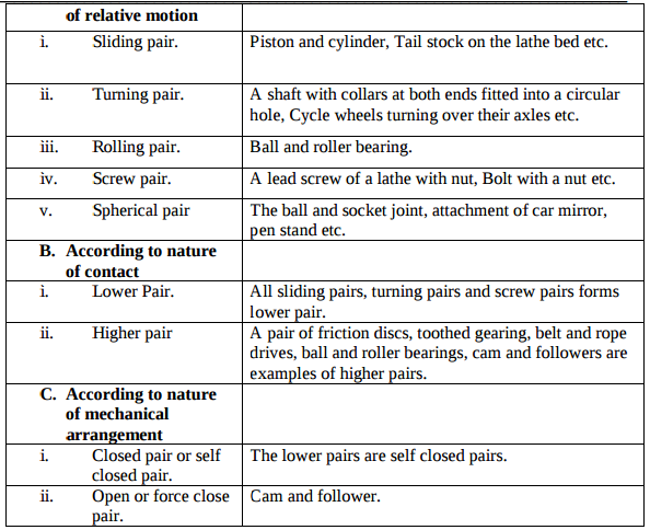
What are the types of kinematic pair ? Give its examples. Answer:
  |
4 |
view |
| Q 2 c ) |
Question:
Define linear velocity, angular velocity, absolute velocity and state the relation between linear velocity and angular velocity. Answer:
|
4 |
view |
| Q 2 d ) |
Question:
Explain the Klein's construction to determine velocity and acceleration of single slider crank mechanism. Answer:
   |
4 |
view |
| Q 2 e ) |
Question:
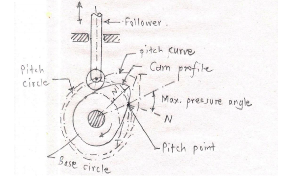
Draw neat sketch of radial cam with follower and show on it (i) Base circle. (ii) Pitch point. (iii) Prime Circle. (iv) Cam profile Answer:
 |
4 |
view |
| Q 3 c ) |
Question:
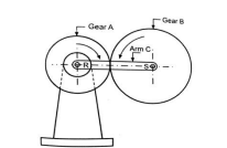
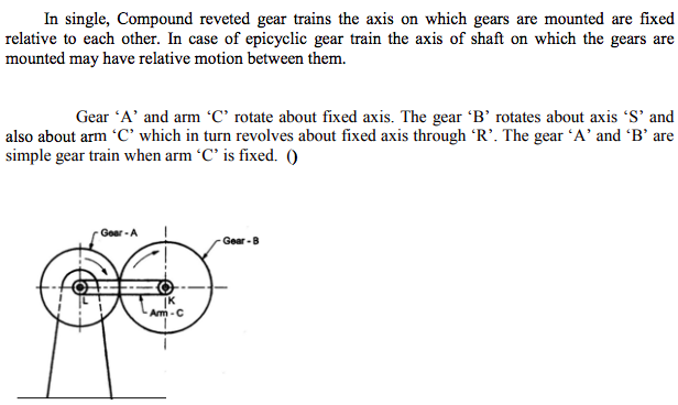
Explain epicyclic gear train with neat sketch. Answer:
 |
4 |
view |
| Q 3 d ) |
Question:
Draw a labelled sketch of multiplate clutch and state its applications. Answer:
 |
4 |
view |
| Q 3 e ) |
Question:
Write the procedure of balancing single rotating mass when it balance mass is rotating in the same plane as that of disturbing mass. Answer:
 |
4 |
view |
| Q 3 f ) |
Question:
What are the different types of follower motion ? Also draw displacement diagram for uniform velocity. Answer:
|
4 |
view |
| Q 4 b ) |
Question:
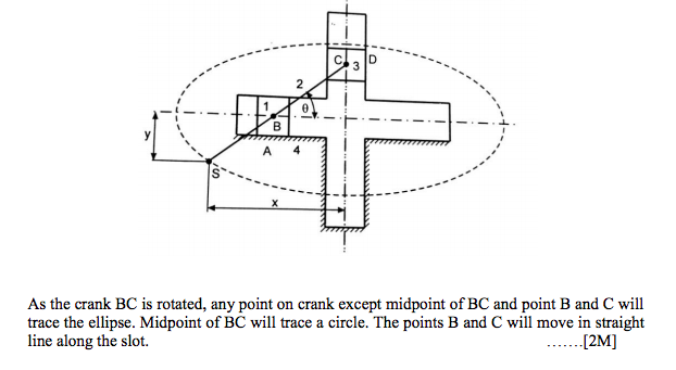
Justify with neat sketch elliptical trammel as an inversion of double slider crank chain. Answer:
|
4 |
view |
| Q 4 c ) |
Question:
Differentiate between flywheel and governor. Answer:
|
4 |
view |
| Q 4 d ) |
Question:
Explain construction and working of eddy current dynamometer. Answer:
 |
4 |
view |
| Q 5 a ) |
Question:
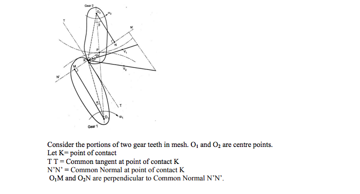
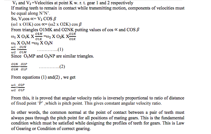
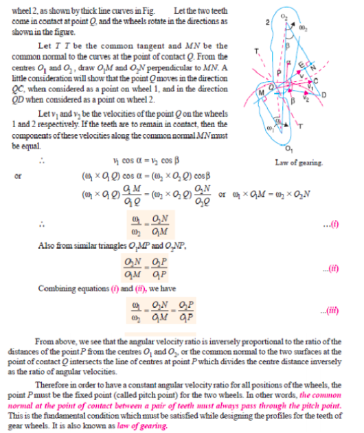
State and explain Law of Gearing. Answer:
|
4 |
view |
| Q 6a)(i) |
Question:
Explain steep and creep phenomenon in belts. Answer:
|
4 |
view |
| Q 6a)(ii) |
Question:
Explain single cylinder 4-stroke I.C. engine using turning moment diagram. Answer:
|
4 |
view |
| Que.No | Question/Problem | marks | Link |
|---|---|---|---|
| Q 1b)(i) |
Question:
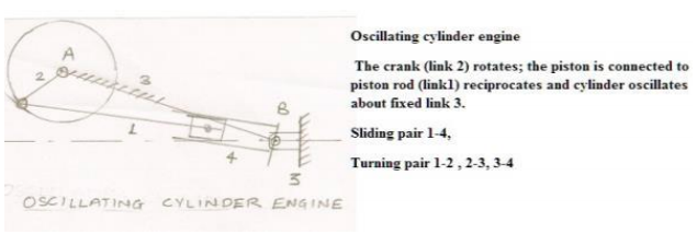
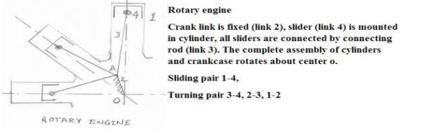
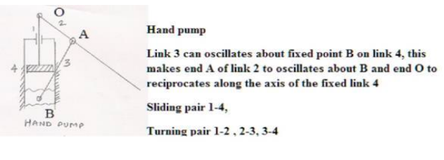
State any four inversions of single slider crane chain. Describe any one with neat sketch. Answer:
|
4 |
view |
| Q 1b)(ii) |
Question:
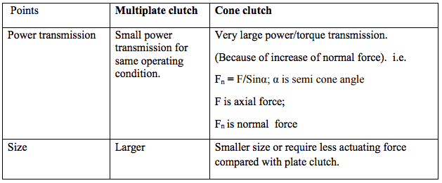
Compare multiplate clutch with cone clutch on the following basis. (1) Power Transmission (2) Size Answer:
|
4 |
view |
| Q 2 a ) |
Question:
Explain a scotch yoke mechanism with a neat sketch. Answer:
 |
4 |
view |
| Q 2 b ) |
Question:
What is machine ? Differentiate between a machine and a structure. Answer:
 |
4 |
view |
| Q 2 c ) |
Question:
Explain Klein’s construction to determine velocity and acceleration of different links in single slider crank mechanism. Answer:
|
4 |
view |
| Q 2 d ) |
Question:
Define the terms: (i) Linear velocity (ii) Angular velocity (iii) Absolute velocity (iv) Relative velocity Answer:
 |
4 |
view |
| Q 2 d ) |
Question:
Explain with neat sketch different types of follower. Answer:
 |
4 |
view |
| Q 3 a ) |
Question:
Discuss the following motion of the follower by drawing the displacement velocity and acceleration diagram. (i) Uniform Velocity (ii) Simple Harmonic Motion (iii) Uniform acceleration and retardation Answer:
   |
4 |
view |
| Q 3 b ) |
Question:
The crank and connecting rod of steam engine are 0.5m and 2m long respectively. The crank makes 180r.p.m. in clockwise direction. When it has turned through 45° from I.D.C. Find the velocity of piston and angular velocity of connecting rod by relative velocity method. Answer:
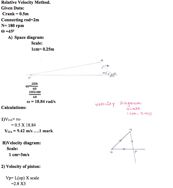 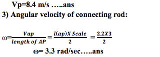 |
4 |
view |
| Q 3 c ) |
Question:
Compare cross belt drive and open belt drive on the basis of - (i) Velocity ratio (ii) Direction of driven pulley (iii) Application (iv) Length of belt drive Answer:
 |
4 |
view |
| Q 3 d ) |
Question:
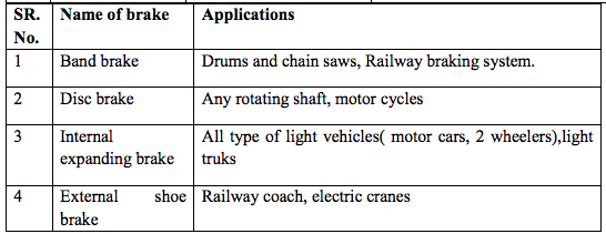
State the applications of : (i) Band brake (ii) Disc brake (iii) Internal expanding shoe brake (iv) External shoe brake Answer:
 |
4 |
view |
| Q 3 f ) |
Question:
Explain with neat sketch working principle of epicyclic gear train. Answer:
 |
4 |
view |
| Q 4 a ) |
Question:
Generally, the lower side is kept “Tight side” and upper side is kept as “Slack side” with the belt drives having small driving pulley and big driven pulley. Why ? Answer:
|
4 |
view |
| Q 4 b ) |
Question:
Describe with neat sketch the working of Oldham’s coupling. Answer:
 |
4 |
view |
| Q 4 c ) |
Question:
Distinguish between flywheel and governor. Answer:
 |
4 |
view |
| Q 4 d ) |
Question:
Discuss the working of Rope brake dynamometer with the help of a neat sketch. Answer:
 |
4 |
view |
| Q 4 e ) |
Question:
Explain the working of internal expanding shoe brake with the help of neat sketch. Answer:
 |
4 |
view |
| Q 4 f ) |
Question:
Explain the process of balancing of single rotating mass by a single mass rotating in the same plane. Answer:
|
4 |
view |
| Q 6a)(i) |
Question:
Define the following terms as applied to cam with neat sketch. (1) Pitch circle (2) Pressure angle (3) Stroke of follower (4) Module Answer:
|
4 |
view |
| Q 6a)(ii) |
Question:
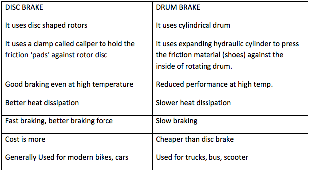
Differentiate between disc brake and internally expanding brake. Answer:
 |
4 |
view |
| Que.No | Question/Problem | marks | Link |
|---|---|---|---|
| Q 1b)(a) |
Question:
Define completely constrained motion and successfully constrained motion with neat sketch. State one example of each. Answer:
 |
4 |
view |
| Q 1b)(b) |
Question:
Explain working principle of clutch. State its location in transmission system of an automobile. Answer:
|
4 |
view |
| Q 1b)(c) |
Question:
Compare cross belt drive and open belt drive on the basis of (i) velocity ratio (ii) application (iii) direction of driven pulley (iv) length of belt drive Answer:
|
4 |
view |
| Q 2 a ) |
Question:
Differentiate machine and structure on any four points. Answer:
 |
4 |
view |
| Q 2 b ) |
Question:
Explain with neat sketch working principle of Oldham’s coupling. Answer:
 |
4 |
view |
| Q 2 c ) |
Question:
Define linear velocity, angular velocity, absolute velocity and state the relation between linear velocity and angular velocity. Answer:
 |
4 |
view |
| Q 2 d ) |
Question:
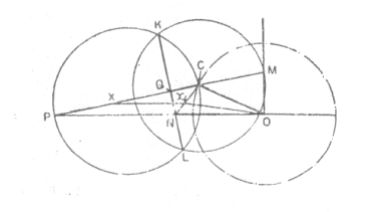
Describe stepwise procedure for determination of velocity and acceleration by Klein’s construction with suitable data. Answer:
|
4 |
view |
| Q 2 e ) |
Question:
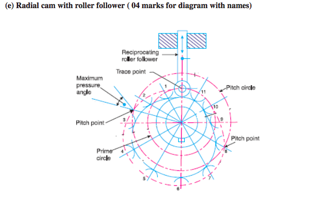
Draw a neat sketch of radial cam with roller follower and show the following on it : (i) Pitch point (ii) Pressure angle (iii) Prime circle (iv) Trace point Answer:
 |
4 |
view |
| Q 3 a ) |
Question:
Draw a neat labelled sketch of “Multiplate Clutch”. Answer:
 |
4 |
view |
| Q 3 b ) |
Question:
Why roller follower is preferred over a knife follower ? State two advantages and application of roller follower. Answer:
|
4 |
view |
| Q 3 c ) |
Question:
Write the procedure for balancing of a single rotating mass by single masses rotating in the same plane. Answer:
 |
4 |
view |
| Q 3 d ) |
Question:
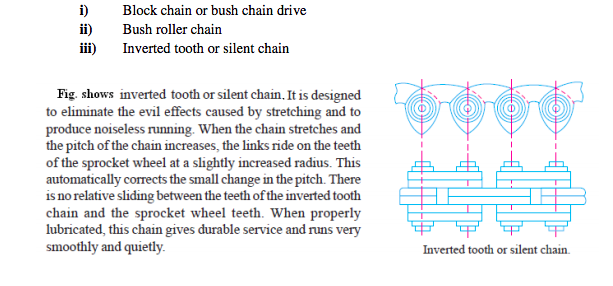
State the type of power transmission chains. Describe any one with its sketch. Answer:
|
4 |
view |
| Q 4 a ) |
Question:
Explain the phenomenon of slip and creep in a belt drive. State its effect on velocity ratio. Answer:
|
4 |
view |
| Q 4 b ) |
Question:
Explain with the diagram working of crank and slotted lever quick return mechanism. Answer:
|
4 |
view |
| Q 4 c ) |
Question:
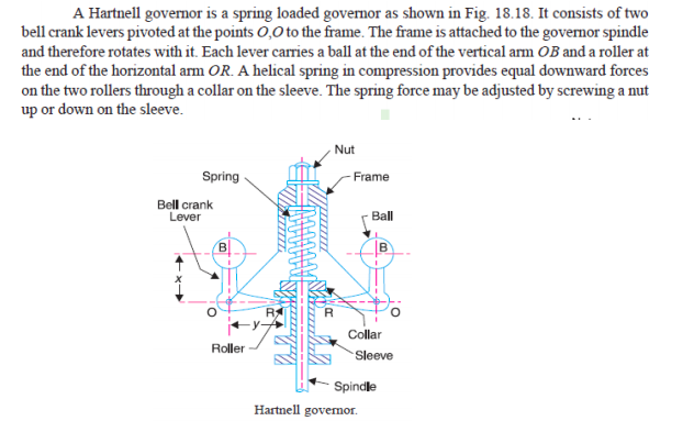
Explain with sketch working of hartnell governor. Answer:
 |
4 |
view |
| Q 4 d ) |
Question:
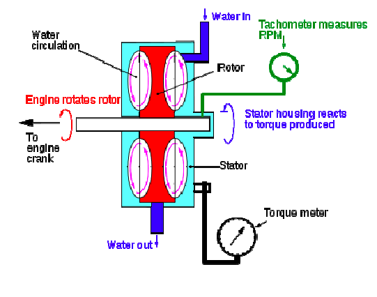
Explain working of hydraulic brake dynamometer with sketch. Answer:
 |
4 |
view |
| Q 6a)(ii) |
Question:
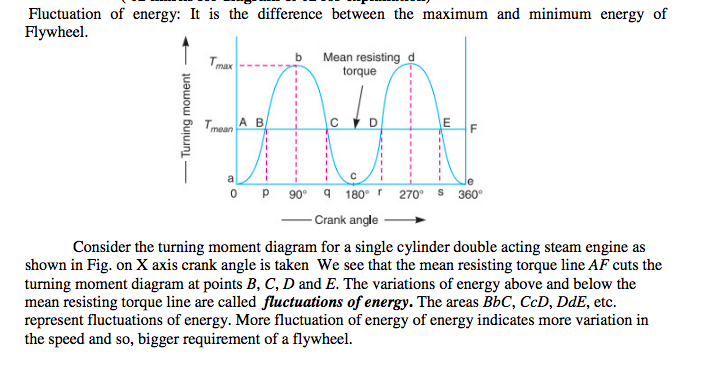
Explain the concept of fluctuation of energy related with turning moment diagram with sketch. Answer:
 |
4 |
view |

| Que.No | Question/Problem | marks | Link |
|---|---|---|---|
| Q 1b)(iii) |
Question:
Draw the neat sketch of epicyclic gear train and explain how it works. Answer:
|
4 |
view |
| Q 2 a ) |
Question:
State and explain various types of constrained motions with suitable examples. Answer:
|
4 |
view |
| Q 2 b ) |
Question:
Draw the neat labeled sketch of Oldham’s coupling. State its applications. Answer:
|
4 |
view |
| Q 2 c ) |
Question:
Define the terms linear velocity, relative velocity, angular velocity and angular acceleration. Answer:
 |
4 |
view |
| Q 2 d ) |
Question:
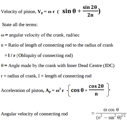
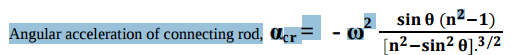
For a single slider crank mechanism , state the formulae to calculate by analytical method – Also state the meaning of each term. Answer:
|
4 |
view |
| Q 2 e ) |
Question:
Define the following terms related to cams. Answer:
|
4 |
view |
| Q 3 a ) |
Question:
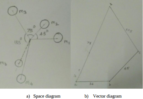
Space diagram 01 Mark, Velocity Diagram 02 marks , Calculations 01 Mark Note In QP length BC & AB are equal. Read length AD = length BC = 150 mm Answer:
 |
4 |
view |
| Q 3 b ) |
Question:
In a single slider crank mechanism, crank AB = 20 mm and connecting rod BC = 80 mm. Crank AB rotates with uniform speed of 1000 rpm in anticlockwise direction. Find (i) angular velocity of connecting rod BC and (ii) Velocity of slider C when crank AB makes angle of 60° with the horizontal. Answer:
|
4 |
view |
| Q 3 c ) |
Question:
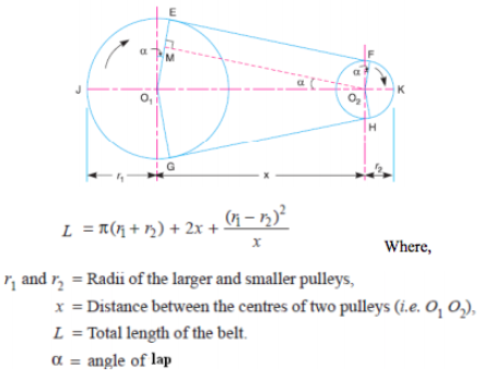
State the formulae to calculate the length of open belt drive and cross belt drive. State the meaning of each term by drawing suitable diagrams in both cases. Answer:
|
4 |
view |
| Q 3 d ) |
Question:
Draw the neat sketch of single plate clutch and explain its working. Answer:
  |
4 |
view |
| Q 3 e ) |
Question:
State the procedure of balancing single rotating mass when its balancing mass is rotating in the same plane as that of disturbing mass. Answer:
 |
4 |
view |
| Q 3 f ) |
Question:
Give detailed classification of followers. Answer:
  |
4 |
view |
| Q 4 a ) |
Question:
What is centrifugal tension ? State its formula. Explain its effect on power transmitted by a belt drive. Answer:
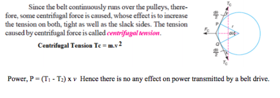 |
4 |
view |
| Q 4 b ) |
Question:
State the meaning of sliding pair, turning pair, rolling pair and spherical pair with one example each. Answer:
 |
4 |
view |
| Q 4 c ) |
Question:
Draw turning moment diagram for single cylinder four stroke I.C. Engine. Label all parts. Answer: |
4 |
view |
| Q 4 d ) |
Question:
Explain the working of rope brake dynamometer with neat sketch. Answer:
  |
4 |
view |
| Q 4 e ) |
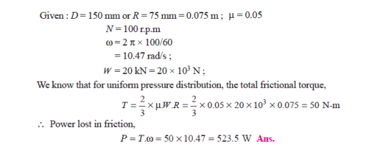
Question:
A vertical shaft 150 mm in diameter and rotating at 100 rpm rests on a flat end footstep bearing. The shaft carries vertical load of 20 kN. Assuming uniform pressure distribution and coefficient of friction equal to 0.05, estimate power lost in friction Answer:
 |
4 |
view |
| Q 4 f ) |
Question:
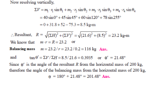
Four masses m1, m2, m3 and m4 are 200 kg, 300 kg, 240 kg, and 260 kg respectively. The corresponding radii of rotation are 0.2 m, 0.15 m, 0.25 m and 0.3 m respectively and the angles between successive masses are 45°, 75° and 135°. Find the position and magnitude of balance mass required, if its radius of rotation is 0.2 m. Answer:
  |
4 |
view |
| Q 6a)(i) |
Question:
State and explain law of gearing with the help of suitable sketch. Answer:
  |
4 |
view |
| Q 6a)(ii) |
Question:
Compare flywheel and governor. Answer:
 |
4 |
view |