What are the advantages of pneumatic system over hydraulic systems ?
1. Incompatibility of seal material with operating system 2. Excessive heat 3. Excessive load 4. Excessive clearance 5. Excessive pressure 6. Improper fitting 7. Improper groove geometry 8. Abrasion 9. Wear
Explain with neat sketch (position based ) working of sequencing circuit for two double acting Air cylinders. Pneumatic double acting cylinders can be operated sequentially using a sequence valve or by using position based method. In pneumatics, use of sequence valve is not popular. Position based sequencing is possible using roller operated DCV or solenoid operated DCV. Various components required for Position based sequencing using roller operated DCV are as follows. I. Double acting cylinder - 02 Nos. II. 3/2 roller operated DCV – 02 Nos. III. 4/2 or 5/2 DCV – 01 No. IV.
.Draw and Explain pneumatic meter in circuit to control of speed extension. In meter in pneumatic circuit flow control valve with check valve is fitted between DCV and actuator. For speed control of actuator during extension stroke, FCV with check valve is fitted on piston side of the actuator as shown in figure. With a meter-in circuit, fluid enters into the actuator at a controlled rate. Pneumatic circuit diagram for meter-in flow-control circuit is as shown in figure. In this circuits, the rate of flow of compressed air into the cylinder is controlled by flow control
List the Factors to be considered for selecting the pipe while designing pneumatic system. Give specification of pipes for the pneumatic system. Factors to be considered while selecting the pipe for pneumatic system 1. Pressure of compressed air in the line. 2. Total flow rate per unit time through the line. 3. Permissible pressure drop in the line. 4. Type of tube material and type of line fittings. 5. Length and diameter of tube or other pipelines. 6. Working environment. Pipe Size Specifications: Generally pipe size is specified in three ways 1.
) Explain with neat sketch working of variable displacement vane pump. In a hydraulic system the flow rate of the pump needs to be variable this can be easily achieved by varying the rpm of the electric motor. Other method is displacement of a vane inside the pump and therefore its delivery is proportional to the eccentricity between the rotor axis and cam ring. Changing the geometric position of the ring relative to the rotor center will change the delivery volume as per system need. Main components of the vane pumps are: 1. Hardened cam ring 2. Rotor 3. Vanes 4.
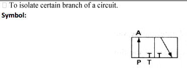
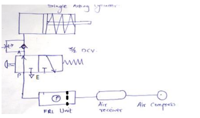
To start, stop and change the direction of motion of a Single acting cylinder. (Clamping of Job)