You are here

2017 SUMMER

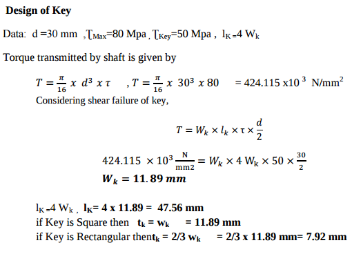
A shaft 30 mm. diameter is transmitting power.....................

Comparison of welded joints with screwed joint. 1) Welded Joint is rigid & permanent. Screwed joint is temporary. 2) Cost of welded assembly is lower than that of screwed joints. 3) Strength of welded structure is more than screwed joints. 4) For welding joints, highly skilled worker are required 5) Welded joints are tight & leak proof as compared to Screwed joints. 6) Welded joint is very difficult to inspect compared to other joints.


Compare welded joints with screwed joints. (Any six points)

Consideration in design of key: 1) Power to be transmitted. 2) Tightness of fit 3) Stability of connection 4) Cost 5) Crushing failure of key: 6) shearing failure of key 7) Material of key ,shaft should be same but key should be weaker than shaft .

Design a foot brake lever from the following data: Length of lever from C.G. of the spindle to the point of application of the load = 1 meter. Max. load on the foot plate = 800 N Overhang from the nearest bearing = 100 mm Permissible tensile and shear str

Methods of reducing stress concentration in cylindrical members with holes . Stress concentration can be reduced in cylindrical members with holes by providing additional holes in vicinity of holes as shown in fig. (ii). Fig (i) Showing cylindrical member with hole at center having stress line in disturb manner at vicinity of hole and component will fail at hole so for fig (i) ,stress concentration is more . fig. (ii) members shoulder having additional hole in vicinity of hole and therefore stress line maintain spacing between them so here stress concentration is less.

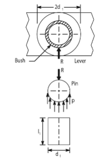
Why are bushes of softer material inserted in the eyes of levers?

the forces acting on the boss of lever & the pin are equal & opposite .There is a relative motion between the pin & the lever and bearing pressure becomes design criteria. The projected area of the pin is d1 x l1therefore Reaction R= P (d1 x l1 ). A softer material like phosphorous bronze bush with 3 mm thick is fitted in eyes to reduce the friction. & bear a bearing pressure upto5 to 10 N/mm2. Bushes are cheaper and can be easily replaceable.

Draw neat sketch of a protected type flanged coupling showing all details.

distance to some degree. c) For effective conjugate action i.e for maintaining a constant velocity ration, in case of involute gearing system, the center distance can be changed without affecting angular velocity ratio. d)In involute gearing as the path of contact is a straight line and the pressure angle is constant .

Sketch of Protected type flanged coupling with details :


State and explain two most important reasons for adopting involute curves for a gear tooth profile


For power transmission gears, the tooth form most commonly used the involute profile as a)Involute gears can be manufactured easily: Since the rack in an involute system has straight sides and since the generating cutters usually have rack profile, these cutters can be easily manufactured. Involute gears can be produced more accurately and at a lesser cost. b) The gearing has a feature that enables smooth meshing despite the misalignment of center

Pages

Subscribe to RSS - 2017 SUMMER