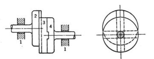
Links: Frame (fixed) :1
Shaft & Flange on left hand :2
Shaft & Flange on right hand :4
Intermediate piece : 3
Pairs: Frame & Shaft LH – turning pair
Frame & Shaft RH – turning pair
Flange LH & Intermediate piece – Sliding pair
Flange RH & Intermediate piece - Sliding pair
Construction : This mechanism is inversion of Double slider Crank Chain .It has two turning & two Sliding pair.
Two flanges with respective shafts are free to rotates with respect to frame both flanges have rectangular slots . An intermediate piece has two rectangular projections on both sides, both projections are perpendicular to each other , each projection fits inside the slot of flange.
Working: When one shaft is given rotary motion,it is transmitted to another shaft the intermediate piece. The intermediate piece slides & adjusts itself, to keep both shafts runnings. The centre of the intermediate piece traces the path of a circle with radius equal to offset between shafts.
Application : This coupling is used to connect two shaft having some eccentricity (offset).