Q.1. Explain with sketch Meter in Circuit and explain its working?
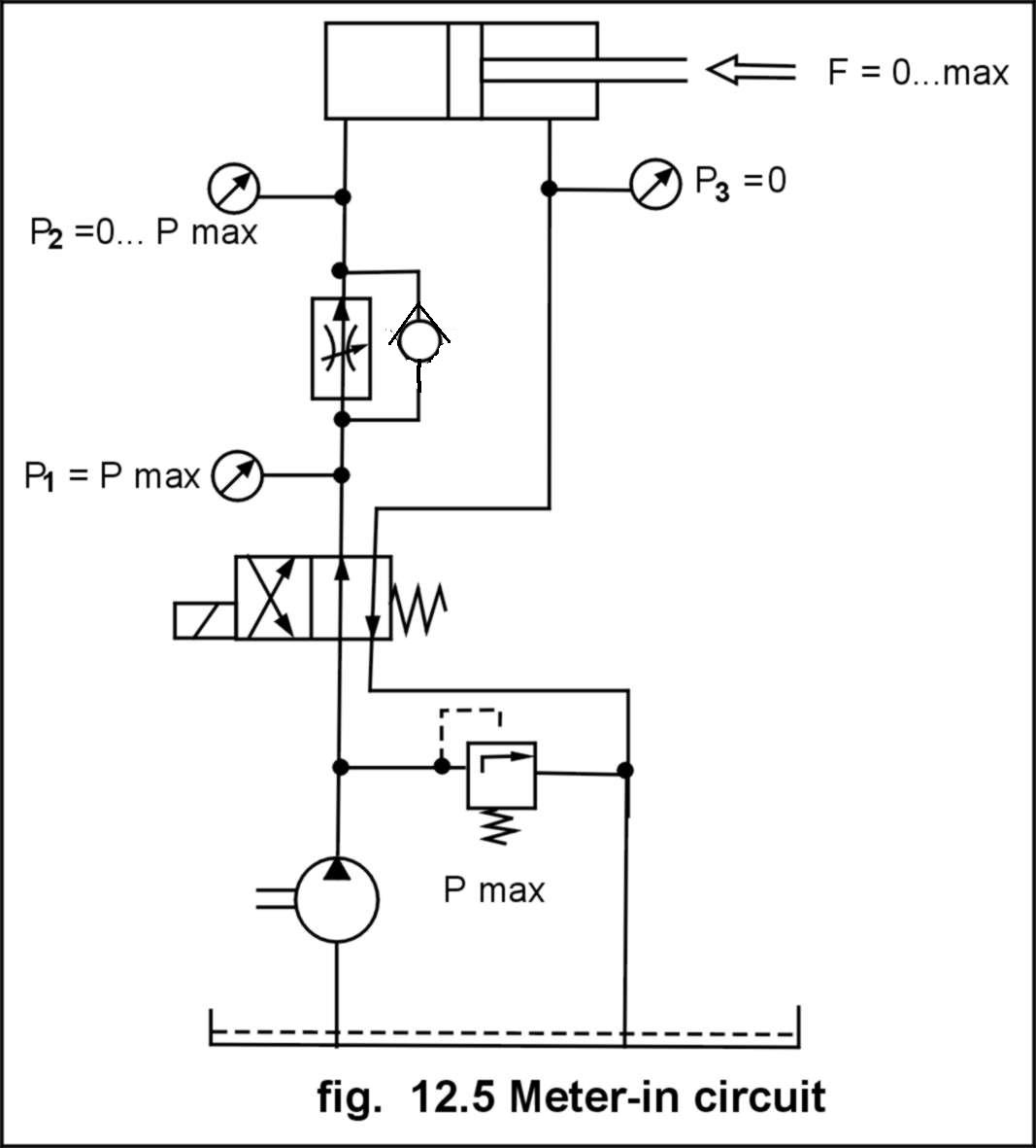
Ans : The fig.below illustrates the circuit connections of a meter-in circuit, in which the flow control valve is placed in the primary line, directly before
the load. Following pressure measures are taken at three different points. In meter-in-circuit speed control is achieved by changing the
flow adjustment of the flow control valve, which controls the oil going to the head end of cylinder. It should be noted that flow
control in given circuit is achieved in forward direction only i.e. in return stroke the return flow from head of cylinder bypasses through check valve.
Advantages of Meter-in-circuit :
The chief advantage of meter-in circuit is that the cylinder undertakes one-sided pressure with a value corresponding to the real load. The relatively small friction (due to pressure on one side, decided by load) of the piston sealing ensures its long life. Uniform motion of the piston rod even at very slow speed.
Flow rate estimation is made based on the large piston area, which is significant advantage when very small piston rod speeds are to be achieved.
Disadvantage of meter-in circuit :The major disadvantage of this circuit lies in the fact that there is no pressure on the piston rod side of cylinder, due to this the load actuated by the piston rod is not held firmly in position. This means that in case of "Pulling” type loads if the load suddenly collapses, the piston rod
shoots forward causing an uncontrolled shift. Special counter balance measures are to be taken if above circuit is to be used for such applications.
Applications of meter-in circuit :
Meters in circuits are generally used when the load characteristics are constant and positive. If the load is erratic or negative, the actuator will have jerky motion. Hence, meter-in circuits are ideally applied on surface grinder, milling machines etc.
Q.2. Explain with sketch Meter Out Circuit and explain its working?
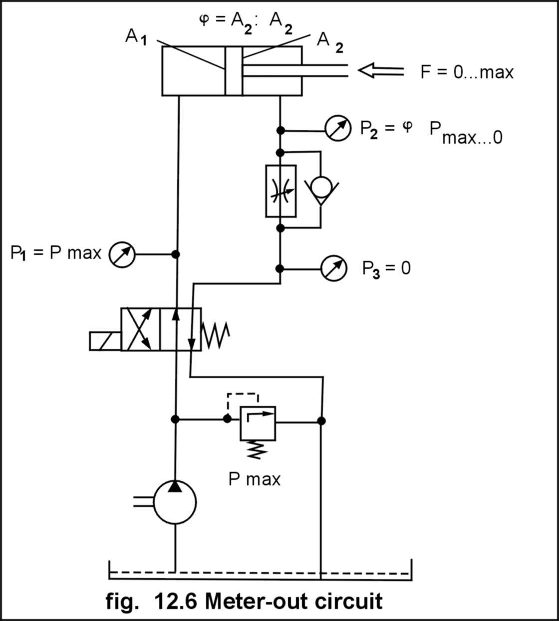
Ans : The Circuit diagram below illustrates the circuit connections of a meter-out circuit, in which the flow control valve is connected in the secondary line, directly
after the load. The following measures of pressure are taken at various pressure gauges.
Pressure
gauge P1 : Indicates the Pmax as set by the pressure relief valve. This pressure is formed on the left side volume of the cylinder, irrespective of the load; hence sealing in this side is always subjected to maximum pressure.
Pressure gauge P2
: Indicates the pressure P2, which is determined by the difference between pressure Pmax and the load pressure. This difference depends on
the ratio of the two-piston areas.
Pressure gauge P3 :Pressure in the return stroke is always equal to 0 . In a meter-out-circuit speed control is achieved by changing the flow adjustment of the flow control valve, which controls the flow coming out
from the piston rod end of cylinder. Here also it should be noted that in a given circuit, flow control is in forward direction only i.e. in return stroke the flow of pump to the piston rod end of cylinder is bypassed through check valve.
Advantage of meter-out circuit : The load is always under pressure from both sides i.e. it is counter balanced.Even when the load changes direction (e.g. starts pulling). No uncontrolled jerk motion occurs.
Disadvantages of meter-out circuit : The left side of the cylinder is always under maximum pressure even with a minimum load. Due to continued pressure on both sides, there is more friction and less seal life.
Applications : Meter-out type circuits are found successful in operations like drilling, boring, reaming etc, where the drills and mills passing through the work piece often tend to drag the entire tool unit foreword, in such situation meter-out circuit is the best solution.
Q.3. Explain with sketch Bleed-Off Circuit and explain its working
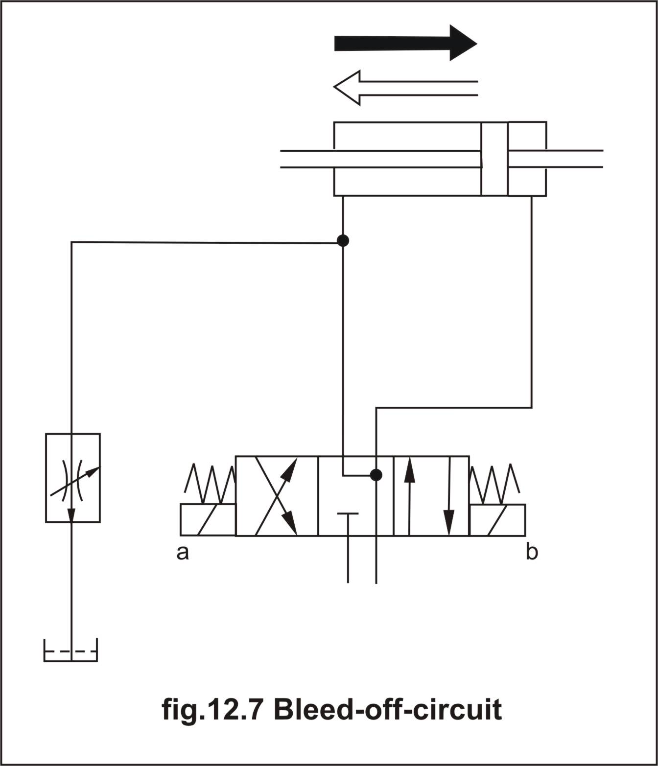
Ans: This is the third basic circuit, which controls neither the flow going to the actuator not flow returning from the actuator but controls the diverted part of fluid to control the flow. In this type of circuit flow control valves are placed in the by-pass line. The cylinder speed in this case is determined by the difference between the pump deliver flow and the flow being directed to the tank
through the flow control valve. The bleed-off valve may be in the
pressure line or in the cylinder line.
Advantage of bleed-off circuit : Unlike in the meter-in and meter-out circuit there is no excess flow going through the pressure relief valve, hence the system ismore efficient and energy saving as well the hydraulic fluid is not heated due to flow through relief valve.
Disadvantages of bleed-off circuit : Bleeds off circuits provide less accuracy in speed control because in these circuits metered flow goes to tank rather than to cylinder. In such type of circuits an individual pump should power each cylinder. A bleed-off circuit is not sensitive enough to compensate for very small flow such as those encountered in precise boring operation
Applications :Bleeds off circuits are applied where pressure is reasonably constant and precise speed control is not the prime requirement. These circuits are widely used in broaching
machines, shapers, planers etc., where a large quantity of fluid is to be used, and small percentage is by passed.
- Log in to post comments